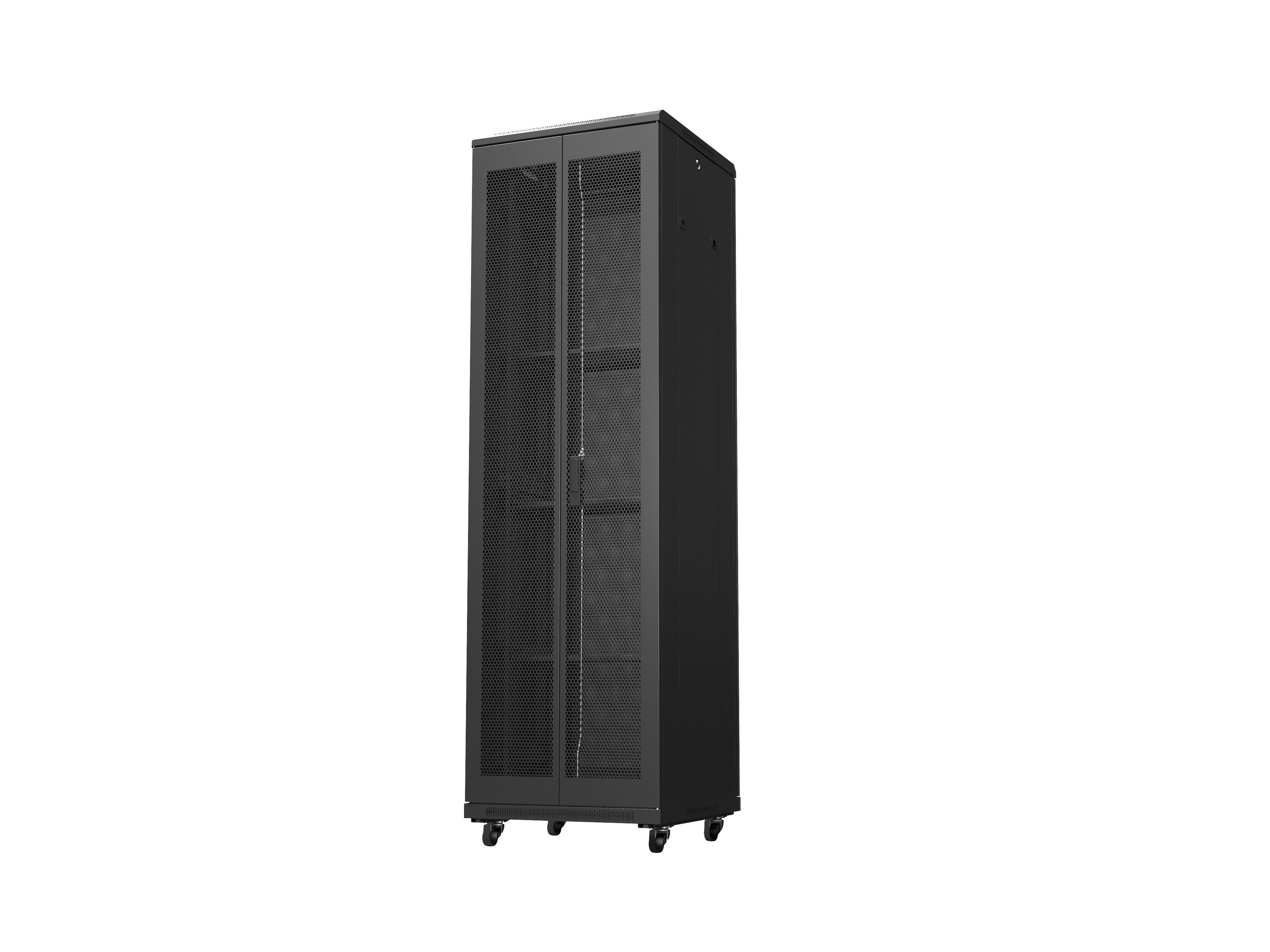
1. Cabinet dimensions: (width) 600mm× (depth) 1200mm (height) 2000mm, available space 42U
2. Load-bearing capacity: The static load-bearing capacity of the cabinet shall not be less than 1800kg. In accordance with the requirements of the standard YD5083-2005(Code for Seismic Performance Testing of Telecommunication Equipment), the cabinet can continuously pass the seismic resistance test of intensity 8 to 9 with a load of 500kg.
3. The thickness of the steel plates used for the main load-bearing components of the cabinet (U-position square hole strips) is all above 2.0mm. The thickness of the steel plates used (for the frame and crossbeams) is all above 1.5mm. The thickness of the steel plates used for the front mesh door, side door, top plate, bottom plate, PDU fixing plate, network cable binding plate and blind plate shall not be less than 1.2mm.
4. The top plate of the cabinet is designed as follows: Behind the closed top plate, there are two incoming line holes equipped with brushes.
5. Cabinet consolidation: The two cabinet columns have consolidation holes on both sides. The consolidation area is flat and sealed, and is randomly equipped with consolidation screws.
6. At the rear of the cabinet, there is a space for heat dissipation and cable routing. The left side is designed as a space for weak current network cables, while the right side is designed to accommodate two PDUs and strong current cables for convenient management and use.
7. On one side of the weak current wiring, a fixing device conducive to vertical cables and horizontal wiring holes should be set up. The most protruding surface of the fixed wire device does not exceed the fixed hole of the square hole strip, which can avoid affecting the plugging and unplugging of the server power supply.
8. The high-voltage wiring space is equipped with a device for fixing vertical PDUs and a wiring hole for binding the server power supply first.
9. Fixed PDU mounting plate, installed near the rear door, to provide a space between the rear side hole strip of the cabinet and the PDU support plate for the binding and placement of longer power supplies first.
10. The installation position of the PDU mounting board is close to the side panel of the cabinet, but at least ensure that the C13 power line can pass through between the PDU mounting board and the side panel of the cabinet (the side panel of the cabinet between parallel cabinets is cancelled). Ensure that after the PDU is installed, the distance between the PDU and the nearest square hole bar is greater than 100mm, which does not affect the plugging and unplugging of the server power supply.
11. A grounding device is installed at the lower right corner of the front and rear door frames of the 1.11 cabinet. The grounding bolt of the front door is connected to the base, and a grounding network is formed between the bases, which is close to the door frames and does not affect the installation of the equipment on the rack.


 Home
Home